Overview
The development of papa goose started in 2001 with the very start of robotics activities at Constructor University, then still running under the name International University Bremen (IUB). From 2002 on, it was assisted by mother goose, a smaller tracked robot. The nicknames papa- and mother-goose are derived from the fact that they cooperate with a set of small autonomous robots called the goslings.
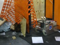
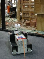
The robots were designed and used in the context of Safety. Security, and Rescue Robotics (SSRR) using the CubeSystem [6]. They participated among others in RoboCup Rescue competitions [1][2][7]. As a special feature, papa and mother goose type robots can be connected with a glass-fiber for data transmission to and from a base-station [16]. The geese were from 2005 on replaced by the RuggedBot design for response robots.
In addition to system development and integration [12] based on the RoboCube [6], research with the geese included mapping [8][10][11][15], exploration [9][13], (shared-)autonomy [3][4][14], and human robot interfaces (HRI) [5].
Papa Goose
Locomotion
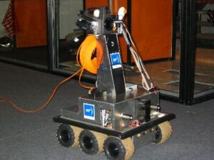
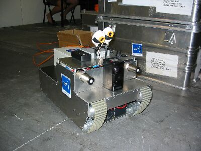
Papa-goose is based on a differential six-wheel drive. It is rather large with a footprint of 450mm × 400mm to allow for a full-fledged PC in addition to its sensors and drive components as well as a significant payload. Its on-board batteries allow for roughly 1 hour of intensive use in difficult terrain and up to 5 hours of operation with sparse locomotion.
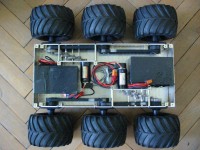
Its locomotion system is a differential drive with six wheels that behaves similar to a tracked drive. The three wheels of each side are driven via belts and a motor-unit connected to the axis of the rear, respectively front wheel on the left, respectively right side of the robot. The first implementation in 2001 was based on a 1:115 spur gear. From 2002 on, the spur gears were replaced by a 66:1 planetary gear-boxes. The motors have 90 W power each and they are equipped with HP quadrature encoder with 500 pulses per channel.
Papa goose is carrying in addition to its CubeSystem an onboard PC. To get an easy start, we chose a standard desktop configuration for this purpose. The on-board PC is hence based on a rather large ATX motherboard with a Pentium III processor running at 1 GHz. The disadvantage of the size is compensated by the 6 PCI slots on the motherboard that allow a significant flexibility for adding cards that can be used to interface various sensors. Already for the most basic configuration of the robot, 3 PCI slots are needed, namely one for a 4-port USB 2.0 extension for cameras, one for a frame grabber for a thermal camera, and one for IEEE 802.11 RF-ethernet.
Sensors and Software
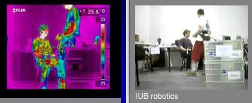
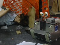
The robots are equipped with four USB cameras with a resolution of 1280×960 pixels. At the RoboCup World-Championship 2003 in Padua Italy, the rescue robot team from Constructor introduced a very special sensor for victim detection into the recue competition, namely a thermal camera. The Flir P60 used on a papa goose has an uncooled, high resolution Focal Plane Array (FPA). Its 320 x 240 elements provide temperature information in a range of -40oC to 120oC with 0.08oC resolution. The color to temperature map can be changed such that the related image highlights only spots with human body temperature. During the competition, the sensor turned out to be very useful as it helps to spot victims under conditions where normal visual feedback completely fails. The standard lens of the camera provides a field of view of 24 deg x18 deg. This field of view was found by our operator to be a bit narrow, especially when compared to the wider opening angles of the normal cameras used on the robots. Hence special optics with field of views of 45 deg x 34 deg were used later on. The main disadvantage of a thermal camera is cost.

Other sensors on the robots are microphones that can also be used to detect victims in rescue scenarios. As obstacle sensors low-cost laser-range-finders (LRF) from Hokuyo Automatic, the PB9-11, are used. It covers 162 degrees in 91 steps up to a depth of 4m. This sensor is the main tool for gathering obstacle data. The bases are in addition equipped with several one-dimensional obstacle sensor, namely coarse range ultrasound sensors with a long range of up to 10 m and a wide scan angle of 60 deg, high precision ultrasound sensors with a medium range of up to 7 m and a narrow scan angle of 10 deg, and active infrared sensors with a short range of up to 0.7 m and narrow scan angle of 10 deg. These sensors are ideal for simple control behaviors like wall-following to autonomously negotiate long corridors. Last but not least, papa goose is equipped with bumpers in form of safety switch tapes. These bumpers are are based on special profile rubber tubes with a highly sensitive switch matrix. The rubber tubes have some shock-absorption capabilities and are thus suited as ultimate safety measure to stop the robot in case that it crashes despite the other sensors into an obstacle.
To estimate the absolute orientation of a papa goose robot, two digital compasses are used. The first one is based on the Philips KMZ51 IC. It has an I2C interface and it is directly connected to the CubeSystem. The second compass is from Honeywell. Its RS232 interface is serviced by the onboard PC. The motors of the robots are equipped with high resolution quadrature encoders from HP. The software modules of the CubeSystem not only use this data for control, but also for odometry and dead-reckoning to estimate the robot’s pose. In doing so, the data from the compass is used for a leaky update of the orientation estimation via odometry. By this, the performance of dead-reckoning gets significantly improved. This can be explained by the fact that the odometry based estimation of orientation severely suffers from cumulative error and hence significantly drifts. The absolute orientation measurements of the compass compensate this drift. Using papa goose robots, the rescue robot team was at the RoboCup World-Championship 2003 in Padua Italy the very first team that managed to autonomously generate map in the unstructured environment of a rescue competition.
Mother Goose
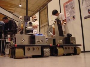
The development of mother goose started in 2002. It was designed to cooperate with papa goose type robots. Mother is tracked robot that is relatively small to allow for high mobility. It has nevertheless quite some on-board computation power and a full sensor payload.
Mother-goose is with a footprint of 400mm × 300mm much slimmer than the papa goose robots and hence suited as an alternative system for more constraint spaces. With its tracked drive, it is designed to negotiate stairs. To save weight and space, mother-goose is equipped with an embedded PC. The locomotion system as well as some of the basic sensors are also implemented with the CubeSystem.
The main design goal for mother goose was to shrink the size of the robot compared to papa goose. This mainly had consequences for the on-board PC, which has to be an embedded solution which fits the size and power constraints. Furthermore, the opportunity to explore an other locomotion system was used and a tracked drive was designed.
The tracked drive of mother goose is based on off-the-shelf belts for power transmission. The belts are double acting, i.e., they have a profile on both the in- and outside and they are therefore especially suited as tracks. The synchroflex belts with T10 profile used for mother goose are available in various lengths and widths. We chose the maximum standard width of 50 mm. The acting length is 1250 mm, leading to a set-up with 480 mm footprint and a front wheel with 127.5 mm elevation above ground. The wheels are standard pulleys. The four bottom wheels are passively rolling along while the elevated front pulley is used to drive the belt and to propel the base.
The locomotion system of mother goose is powered by two motors with 90 W power, a planetary gear-box with 66:1 reduction and quadrature encoder with 500 pulses per channel. The complete motor-units have an overall length of approximately 150 mm. Therefore a transmission is used to mount the motors perpendicularly to the drive axis. For this purpose, universal joints were chosen as they are very lightweight and can transmit high torques. Alternative solutions like bevel gears are much heavier, namely in the order of several kilograms, to transmit the required torques. The universal joints have the disadvantage that they require precise assembly. Slight misalignments already lead to jamming and severe wear-out.
The main voltage of mama goose is 24 V. It is supplied from two lead acid batteries with 7.2 Ah. In addition to its CubeSystem components, mother goose is carrying an embedded PC. Its CPU card runs on a National Semiconductor Geode processor, a GX1 at 300 MHz, with 256 MB SDRAM and a CS5530A chipset. The embedded PC has 2 RS-232 ports, one being used to interface the CubeSystem and one for a Hokuyo laser-range-finder (LRF). The bus board of the PC has two PCI slots. One is used for a WLAN-card, the other one is used for a card providing four USB 2.0 ports, to which the two cameras are connected.
The LRF on mother goose, a Hokuyo Automatic PB9-11, covers 162 degrees in 91 steps up to a depth of 4m. In addition mother goose has two ultrasound sensors with a medium range of up to to 7 m and a narrow scan angle of 10 deg. To estimate the absolute orientation of the robot, two digital compasses are used. The first one is based on the Philips KMZ51 IC. It has an I2C interface and it is directly connected to the CubeSystem. The second compass is from Honeywell. Its RS232 interface is serviced by the onboard PC. The motors of mother goose are equipped with high resolution quadrature encoders. The software modules of the CubeSystem not only use this data for control, but also for odometry and dead-reckoning to estimate the robot’s pose. In doing so, the data from the compass is used for a leaky update of the orientation estimation via odometry. By this, the performance of dead-reckoning gets significantly improved.
Goslings
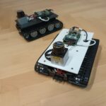
The goslings are small mobile robots. The design is based on a low-cost tracked platform from an RC-toy where the original remote control electronics are replaced by the CubeSystem and range sensors including an laser range finder (LRF) are added. The data is transmitted to a base-station with a PC where it is processed. The footprint and grip of the tracks are very limited. Also, the wireless transmission of the data from multiple robots has its limitations. They were hence never used in RoboCup Rescue competitions but as basic research platforms in the context of cooperative exploration and mapping and later on in a revised version for education [17].
Publications
(If you can not get access to the publication via, e.g., the DOI link, click on [Preprint PDF] to get a preprint copy via ResearchGate)
[1] A. Birk, H. Kenn, M. Rooker, A. Akhil, B. H. Vlad, B. Nina, B.-S. Christoph, D. Vinod, E. Dumitru, H. Ioan, J. Aakash, J. Premvir, L. Benjamin, and L. Ge, “The IUB 2002 Rescue Robot Team,” in RoboCup-02: Robot Soccer World Cup VI, Springer, 2002.
[2] A. Birk, S. Carpin, and H. Kenn, “The IUB 2003 Rescue Robot Team,” in Robocup 2003, Team Description Paper (TDP), 2003.
[3] A. Birk and H. Kenn, “A Rescue Robot Control Architecture for a Rescue Robot ensuring Safe Semi-Autonomous Operation,” in RoboCup 2002: Robot Soccer World Cup VI. vol. 2752, Springer, 2003, pp. 254-262. https://doi.org/10.1007/978-3-540-45135-8_19 [Preprint PDF]
[4] A. Birk, H. Kenn, and M. Pfingsthorn, “The IUB Rescue Robots: From Webcams to Lifesavers,” in 1st International Workshop on Advances in Service Robotics (ASER), Bardolino, Italy, 2003.
[5] H. Kenn, S. Carpin, M. Pfingsthorn, B. Liebald, I. Hepes, C. Ciocov, and A. Birk, “FAST-Robots: a rapid-prototyping framework for intelligent mobile robotics,” in IASTED International Conference on Artificial Intelligence and Applications, Malaga, Spain, 2003, pp. 76-81. [Preprint PDF]
[6] A. Birk, “Fast Robot Prototyping with the CubeSystem,” in International Conference on Robotics and Automation (ICRA), 2004. https://doi.org/10.1109/ROBOT.2004.1302539 [Preprint PDF]
[7] A. Birk, S. Carpin, and H. Kenn, “The IUB 2003 Rescue Robot Team,” in RoboCup 2003: Robot Soccer World Cup VII. vol. 3020, Springer, 2004.
[8] S. Carpin, V. Jucikas, and A. Birk, “Multi-robot mapping for rescue robotics,” in Second IEEE International Workshop on Safety, Security, and Rescue Robotics (SSRR), Bonn, Germany, 2004. [Preprint PDF]
[9] M. Rooker and A. Birk, “Communicative Exploration in Dangerous Environments,” in Second International Workshop on Advances in Service Robotics (ASER’04), Stuttgart, Germany, 2004. [Preprint PDF]
[10] S. Carpin and A. Birk, “Stochastic map merging in rescue environments,” in RoboCup 2004: Robot Soccer World Cup VIII. vol. 3276, Springer, 2005, p. 483ff. https://doi.org/10.1007/978-3-540-32256-6_43 [Preprint PDF]
[11] S. Carpin, A. Birk, and V. Jucikas, “On Map Merging,” International Journal of Robotics and Autonomous Systems, vol. 53, pp. 1-14, 2005. https://doi.org/10.1016/j.robot.2005.07.001 [Preprint PDF]
[12] H. Kenn and A. Birk, “From Games to Applications: Component reuse in Rescue Robots,” in RoboCup 2004: Robot Soccer World Cup VIII. vol. 3276, Springer, 2005, p. p.669ff. https://doi.org/10.1007/978-3-540-32256-6_65 [Preprint PDF]
[13] M. Rooker and A. Birk, “Combining Exploration and Ad-Hoc Networking in RoboCup Rescue,” in RoboCup 2004: Robot Soccer World Cup VIII. vol. 3276, Springer, 2005, pp. pp.236-246. https://doi.org/10.1007/978-3-540-32256-6_19 [Preprint PDF]
[14] A. Birk and S. Carpin, “Rescue Robotics – a crucial milestone on the road to autonomous systems,” Advanced Robotics Journal, vol. 20, pp. 595-695, 2006. https://doi.org/10.1163/156855306776985577 [Preprint PDF]
[15] A. Birk and S. Carpin, “Merging occupancy grid maps from multiple robots,” IEEE Proceedings, special issue on Multi-Robot Systems, vol. 94, pp. 1384-1397, 2006. https://doi.org/10.1109/JPROC.2006.876965 [Preprint PDF]
[16] A. Birk and C. Condea, “Mobile Robot Communication without the Drawbacks of Wireless Networking,” in RoboCup 2005: Robot Soccer World Cup IX. vol. 4020, Springer, 2006, pp. 585 – 592. https://doi.org/10.1007/11780519_57 [Preprint PDF]
[17] A. Birk, “Where else do you see cheering crowds in a classroom?,” IEEE Robotics and Automation Magazine (RAM), vol. 17, p. 20, 2010. https://doi.org/10.1109/MRA.2010.938500 [Preprint PDF]